Control parameters
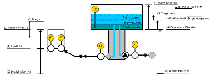
The control limits for the mpc are vectors with length equal to the control horizon. The limits come from a variety of sources, some from user input. In the picture, a conceptualisation for control parameters are shown. The control input condences a lot of information from data handling, network connections, sensor properties, etc. This is all covered in this section, with a focus on a conceptual single distribution well / measuring station and one elevated storage facility.

Minimal pressure
The minimal pressure constraints for a node is computed as:
- P_{min,mpc} is the control limit for the mpc optimisation. This pressure is considered 'absolute'. It represents the total energy stored in the water over a shared reference for all model states with pressure. This is necessary to compute the pressure water must overcome, to arrive at a node with an acceptable service pressure.
- P_{elevation}. Elevation is the vertical distance to a measurement from a reference shared between all measurements.
- P_{min.service}. Service pressure is the minimal acceptable pressure in the model point, expressed as surplus pressure (contrary to absolute pressure). By default this is assumed to be 2 bar.
- P_{margin}. Can be utilised for compensation, if the model has a known weakness or otherwise, that induces a bias. Using the margin can correct the model, while keeping the P_{min.service} and P_{elevation} in line with requirements.
- f. Factor converts bar to water column.
The intention with these parameter options, is that pressure model states by default should be elevation + 2bar. When editing parameters consider:
- A measuring station might not have the same 2 bar surplus pressure requirement, if situated on a transmission line with no consumers.
- A critical pressure point can be handled by increasing the service pressure requirement: If the critical pressure is in an elevated location (likely by definition), the wanted service pressure there can be maintained by increasing the the minimal pressure with the connecting stations.
The margin can be modified with a positive or negative value, as a buffer, depending on the issue it addresses. The neutral setting for margin arguements are always 0.
Control limits for elevated storage
Elevated storage has more parameters than a minimal pressure control element, but is prioritised to be similar in design. A key difference is that elevated storage has a target water level, which is a preferred water level the mpc tries to reach. The control limits are defined as:
$$ L_{min.mpc} [m]=L_{elevation} [m]+L_{max.passive} [m]+L_{passive.margin} [m] $$ $$ L_{max.mpc} [m]=L_{elevation} [m]+L_{max.active} [m]+L_{active.margin} [m] $$
- L_{min.mpc}. Used in mpc and is analogous to P_{min}.
- L_{elevation}. Elevation for elevated storage, as with minimal pressure. The elevation is taken to reference the 0 point of the level gauge in the storage tank, and the shared reference.
- L_{max.passive}. Passive volume is defined as the amount of water that should always be in the storage tank, for operational emergencies, such as fire supply. The parameter is referenced as the minimal water level that the mpc should at least maintain in the tank at all times.
- L_{passive.margin} is an option to add some extra height to the mimimal water level. One intended usage is to add robustness to the control program, if measurements have significant uncertainty or if system is not as responsive as the mpc model.
- L_{max.active} is the top of the active volume, which the mpc can utilise. Is expected to coincide with the height of the tank overflow weir.
- L_{active.margin}. Can be used to prevent the controller to go exactly to L_{max.active}, for same reasons as L_{passive.margin}.
L_{max.passive} and L_{max.active} does not have default settings, but the tank dimensions are useful. The cost function for elevated storage and target level is defined as:
- \rho_L is a ‘cost’ associated with deviating from the target water level, L_{cost}.
- L_{cost} is the desired water level in the storage tank, when accounted for tank elevation.
- L_{target} denne kan indstilles for at give mpc’en en mere midtersøgende strategi. Da det er en afvigelses beregning, giver det ikke fejl selvom L_{target}<L_{passive.margin}, det øger blot straffen. Det bør dog tilstræbes at L_{target} holdes inden for L_{min.mpc} og L_{max.mpc}.
Control limits for pumps
Pumpen har et mindste flow og en kapacitet, samt en ‘cost’ for at ændre arbejdspunkt. Styringsgrænser er defineret:
- Q_{min.mpc} is minimal pumped flow formatted to mpc units.
- Q_{min.flow} is the user paramter set with operational units.
- Q_{min.margin} is a flow that can be added to prevent the pump from going to the true minimum.
- Q_{capacity} is the maximal flow.
Cost function for pumps are defined with a cost for changing the pumped flow:
- \rho_Q is the ’cost’ associated with changing the discharged flow Q_t ´with respect to the previous flow Q_{t-1}, when t is any indexed position in the control horizon.
- N_p is the length of control horizon, in number of indexed position.
- Q is the predicted discharge and Q_0 the latest measuremed discharge.
Discharged flow and pump pressure is correlated with a linear model.